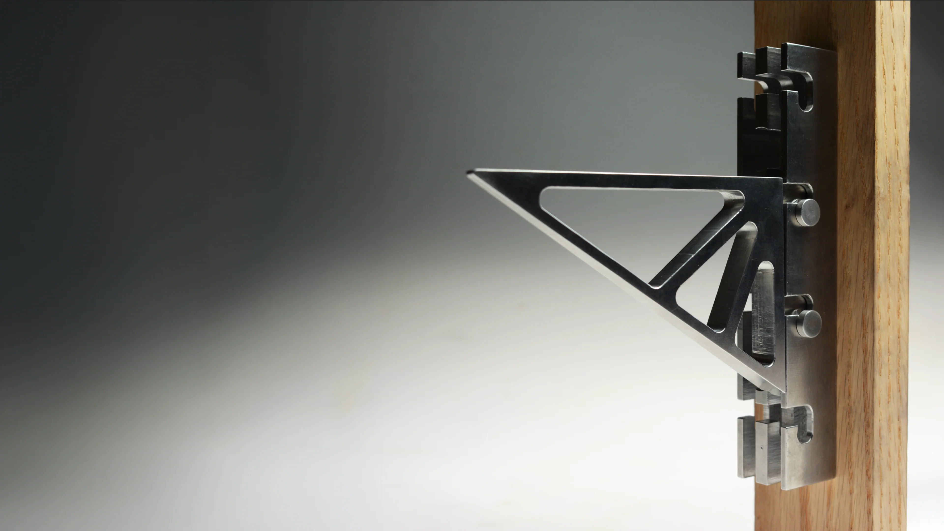
Tekton |
A Modular Wall Mounted
Bracket System
Bracket System
In this project, I was tasked with machining a 3+ part functional assembly. I expanded the project by designing a wall-mounting system.
Josh White | 4 Week Project
[Photo, Uma Freitag]
Inspiration
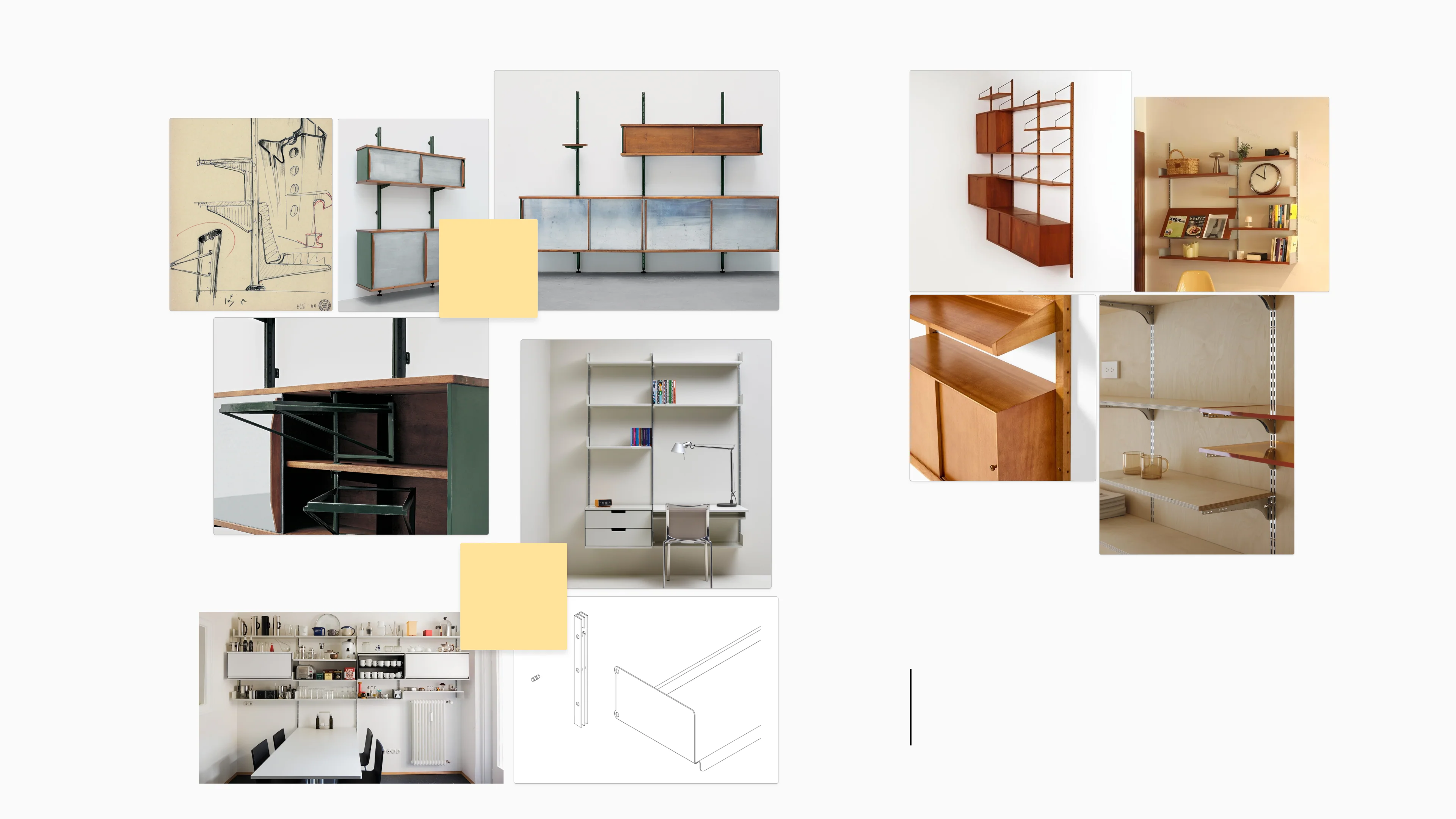
Jean Prouvé|
Wall Mount
Wall Mount
Dieter Rams|
606 Universal
Shelving
System
606 Universal
Shelving
System
After discovering the 20th-century craze for wall-mounted furnishing, a pivotal point in design that pushed flexibility, utility and customisation, I was inspired to design a novel system in my metals manufacturing class.
Form Sketches
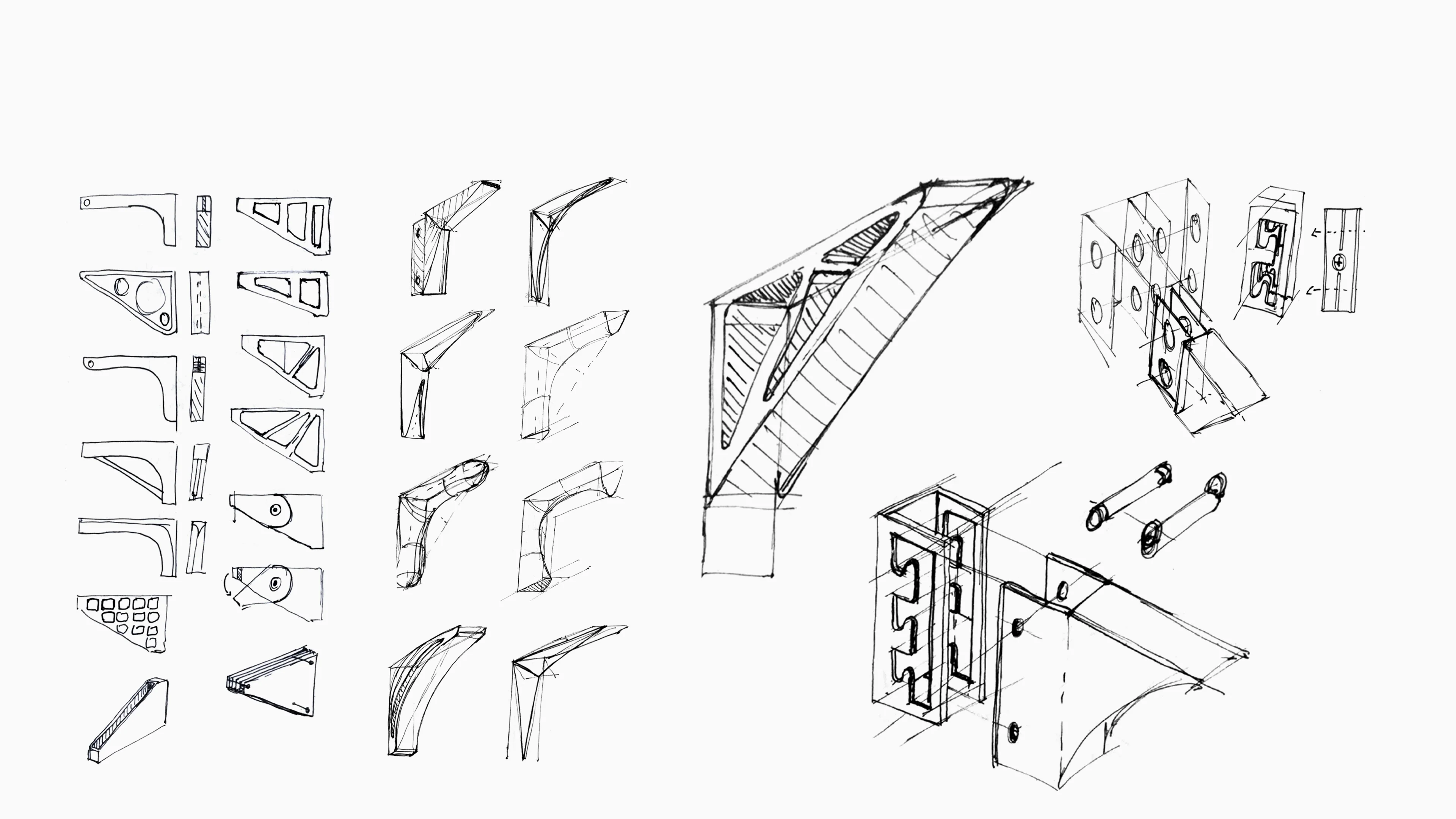
Bracket Ideation
Final Bracket
Rail
CAMing Pin
Bracket
CAD Iterations
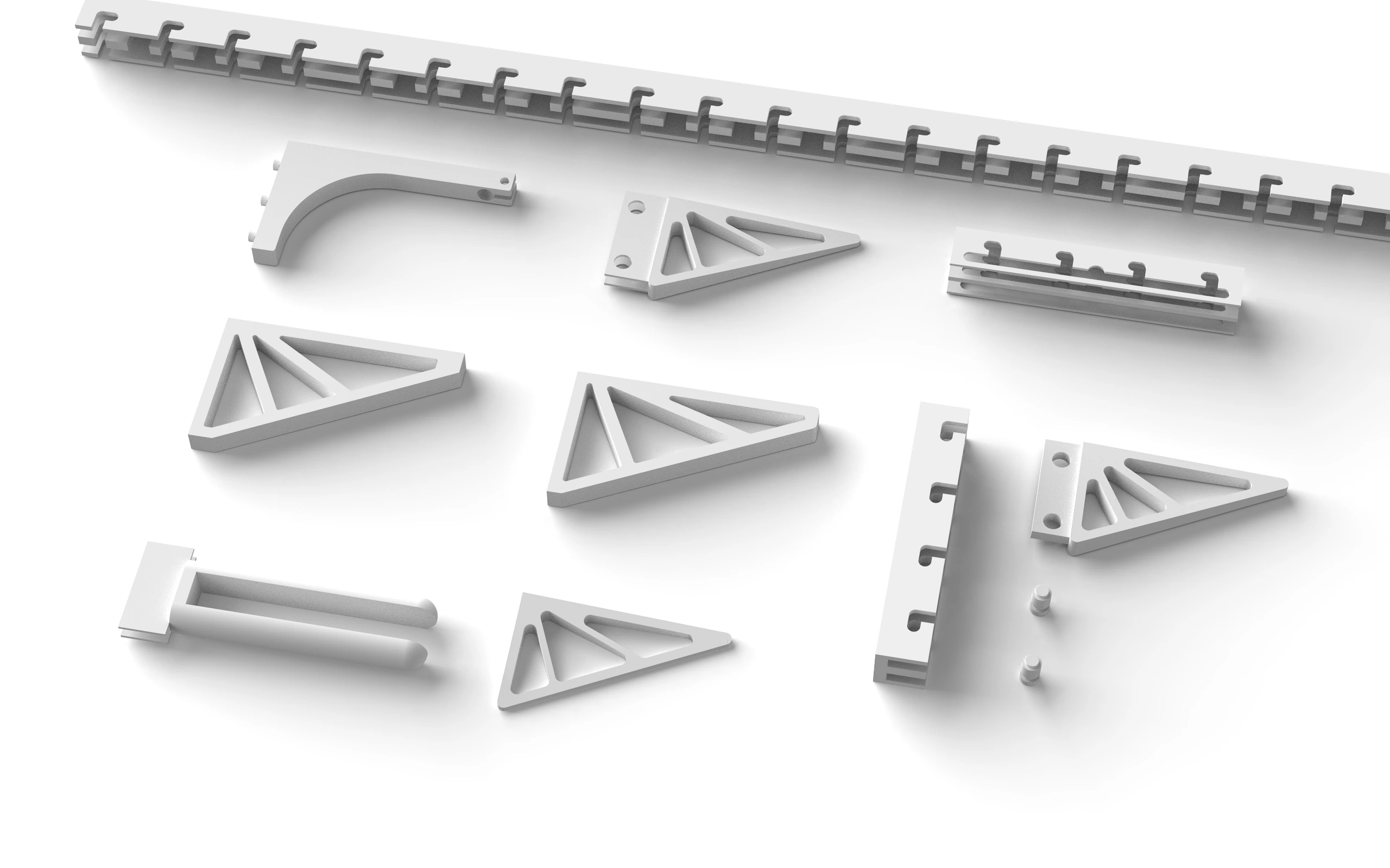
I went through several iterations of CAD modelling, using quick mockups to inform design direction based on my sketches.
Several models were 3D printed to pinpoint scale, proportion and function. A full working model was also printed, including the bracket, rail and pins.
CAM Lock System
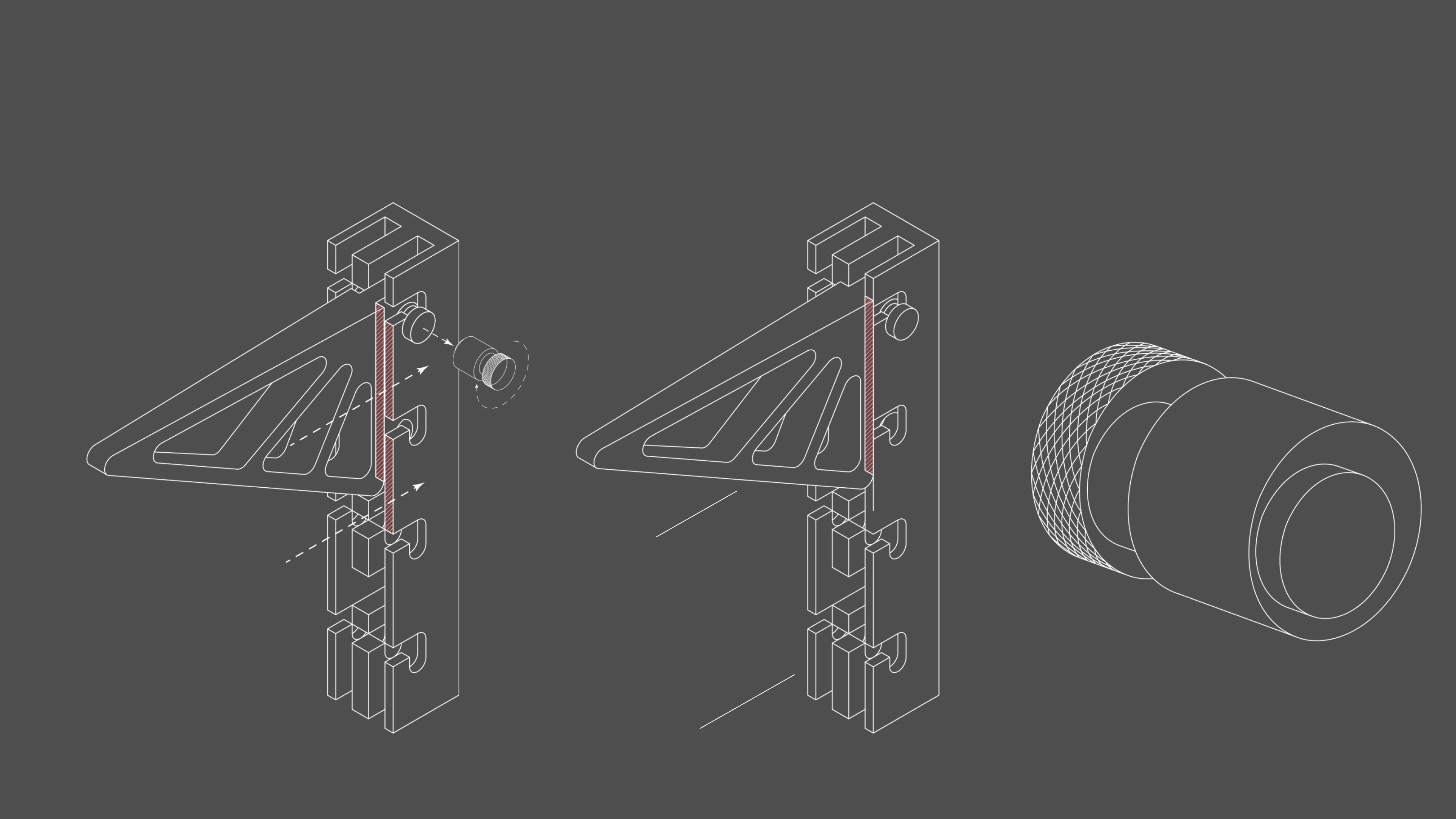
Unlocked Position |
With the CAMing pin unlocked
bracket is loose and not
flush against the rail
bracket is loose and not
flush against the rail
Locked Position |
After the CAM pin is rotated
the bracket is fastened
tightly to the rail.
the bracket is fastened
tightly to the rail.
CAM Locking Pin |
Knurling for additional grip
and 0.125” offset for CAMing
and 0.125” offset for CAMing
*90 Degrees
Bracket |
Rail |
Engineering Drawings
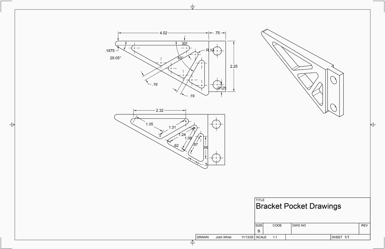
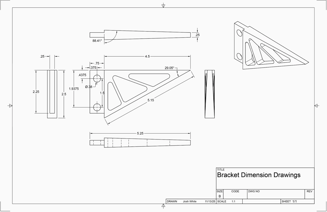
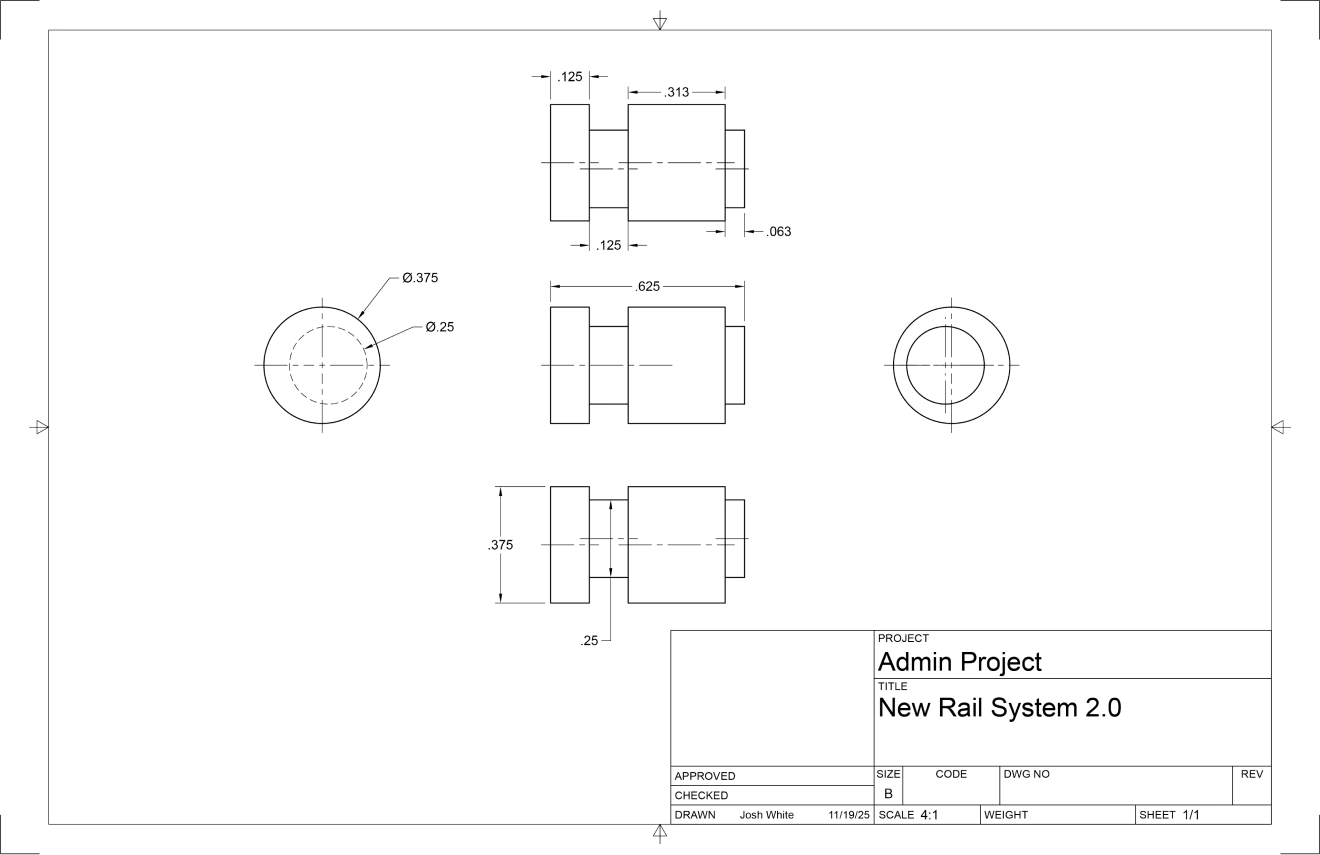
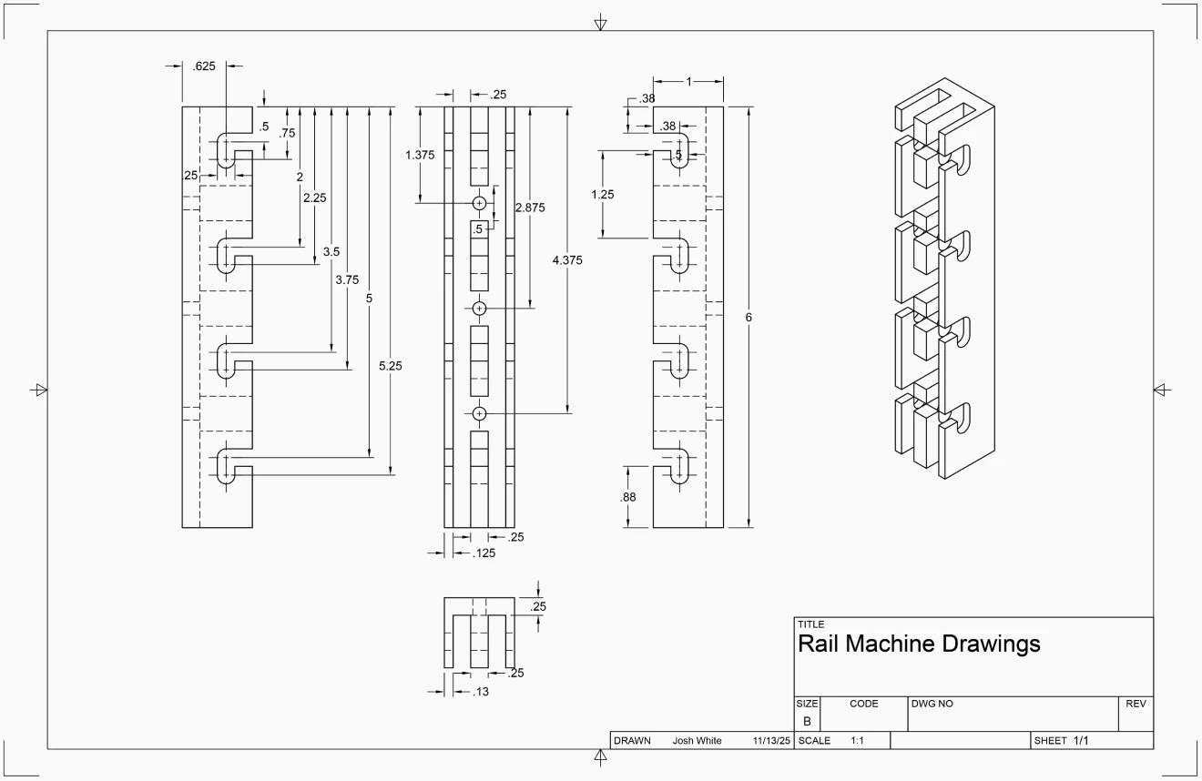
In order to hand machine my bracket system on a Bridgeport mill and lathe, I created engineering drawings for each part, extracted from my Fusion CAD file.
Machining Process
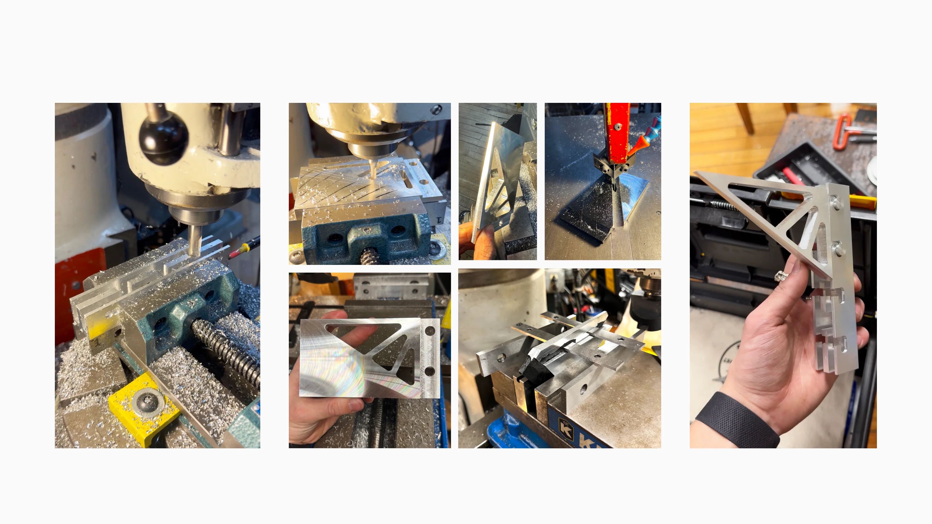
Rail
Shelf Bracket
Pins & Final
Stock was squared and fly cut, then through holes, horizontal slots, plunge cuts and pockets finalised the form.
Notable processes: triangular pockets on a rotary table, 2° tapers with angle blocks, and angled face surfacing using a cutoff to create a square compound angle.
Pins were made using a 1/8" parting tool.
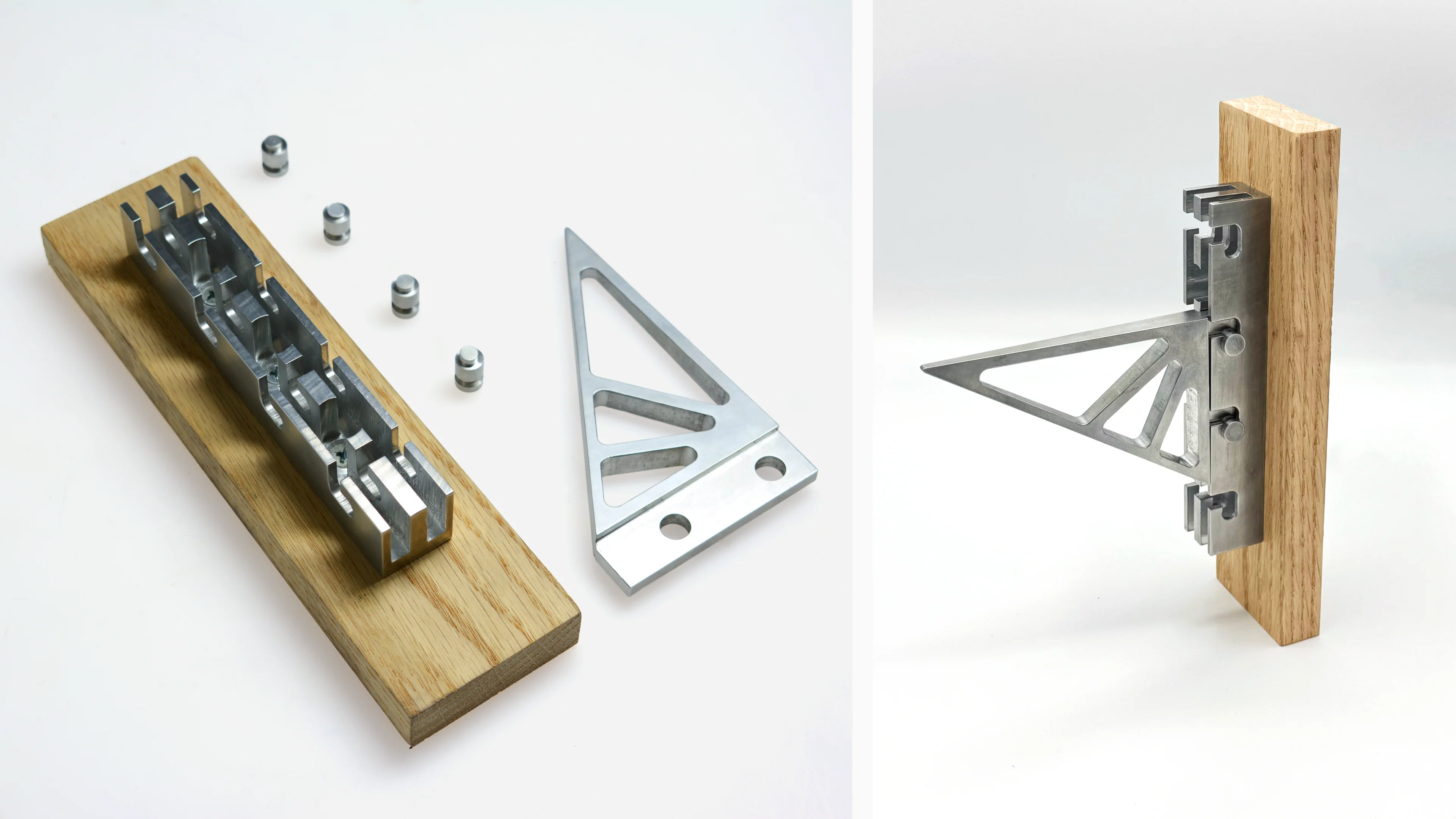
[Photos, Josh White]
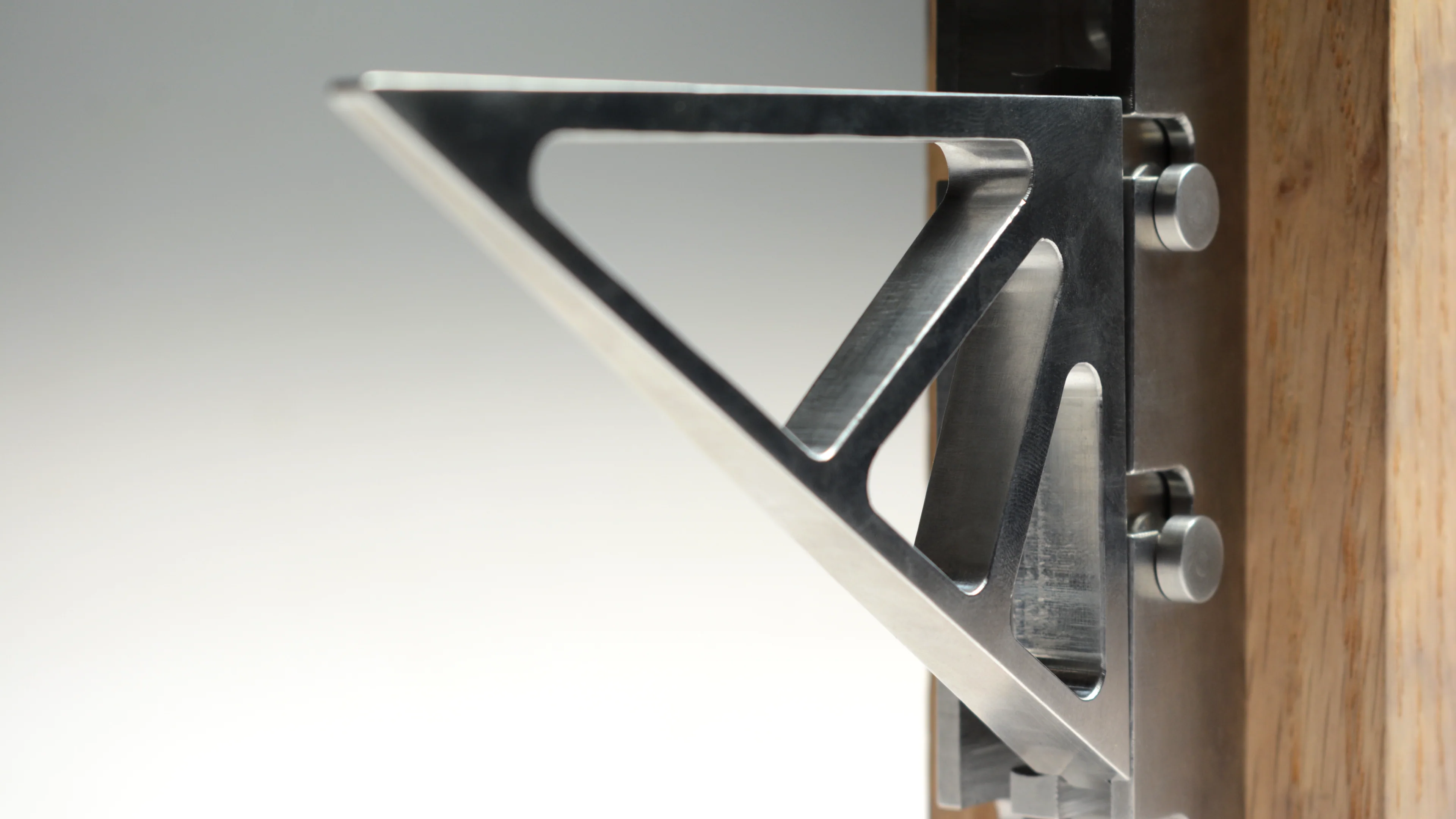
[Photo, Uma Freitag]
In Context
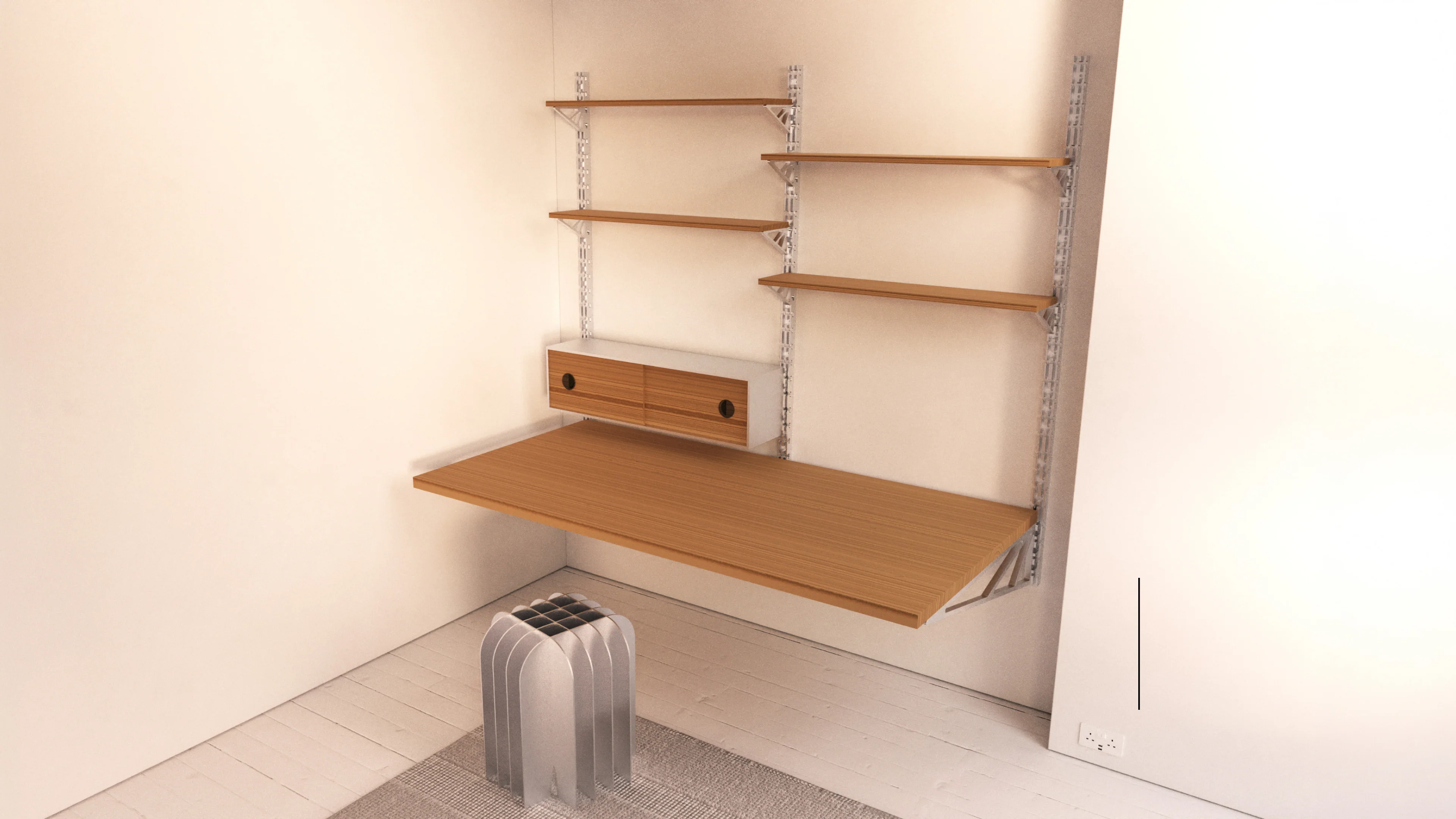
In reality, the bracket system would mount to a wall and allow for the attachment of furnishings like cabinets and desks.
This allows the user to cater to THEIR needs.
This allows the user to cater to THEIR needs.
[Render, Josh White]
Outcome A fully hand-machined, working bracket, rail and cam-pin assembly, extended into a wall-mounted furnishing concept.